

Operating Elements
The figure below shows the tail of the MP-500 and the most important operating elements.
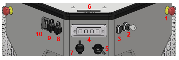
Operating elements of the MP-500
1 Emergency stop buttons 2 Key switch 3 Brake release button 4 Keypad 5 Charging socket 6 LC-Display 7 Wireless joystick receiver 8 USB socket 9 Ethernet socket 10 HDMI socket
Emergency Stop Buttons
When one of these buttons is pressed the robot is immediately set to emergency stop. All drives are disconnected from power supply and the fail-safe brakes are engaged. This state can be reset by unlocking the emergency stop buttons and turning the key switch clockwise to position II for a few seconds.
Key Switch
See Key Switch.
Brake Release Button
Pressing this button will open the motors’ brakes thus allowing the robot to be moved manually even while it is turned off.
Tip
If the control software is running and the emergency stop buttons have not been pressed, the motor amplifiers will still stabilise the robot’s position when pressing the brake release button. In this case at least one of the emergency stop buttons must be pressed before the robot can be moved manually.
Charging Socket
The battery charger can be manually connected to this socket. Further information can be found at Charging.
LC-Display
This display shows the most important status information.
A detailed description of the LCD can be found in LC Display.
Access to the On-Board Computer
The on-board computer can be accessed via an HDMI, a USB and an Ethernet socket.
Keypad
The keypad can be used for simple input and predefined commands. By default it is without function and has to be interpreted by the application control software.