

Mechanical Properties
Dimensions
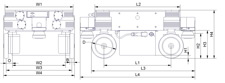
Dimensions of the MPO-700
| Description | Symbol | Value (mm) |
|---|---|---|
| Width of the top plate | W1 | 488 |
| Width of the Omni Drive Module configuration | W2 | 380 |
| Recommended track width | W3 | 470 |
| Maximum width of the platform | W4 | 509 |
| Maximum width of the platform with diagonal scanners | W4’ | 656 |
| Wheel eccentricity of the Omni Drive Modules | O | 45 |
| Width of the wheels | B | 30 |
| Diameter of the wheels | D | 180 |
| Length of the Omni Drive Module configuration | L1 | 480 |
| Maximum length of the platform | L2 | 610 |
| Overall length with one laser scanner | L3 | 741 |
| Overall length with two laser scanners | L4 | 822 |
| Overall length with two diagonal laser scanners | L4’ | 756 |
| Ground clearance with battery | H1 | 23 |
| Height of scan plane | H2 | 181 |
| Ground clearance without battery | H3 | 202 |
| Height of top plate | H4 | 348 |
Absolute Maximum Ratings
Warning
Exceeding these ratings might cause malfunctions or damage the robot!
| Description | Units | Value |
|---|---|---|
| Storage temperature | °C | -20 .. +50 |
| Operating temperature (environmental temperature) | °C | +0 .. +25 |
| Payload | kg | 400 |
| Maximum speed | m/s | 0.9 |
| Maximum bumpiness to pass over (≤ 0.25m/s) | mm | 15 |
| Maximum bumpiness to pass over (full speed) | mm | 5 |
Positions of Sensors
All distances are in millimetres, measured relative to the platform’s coordinate system. All angles are in degrees, measured counter-clockwise from the driving direction.
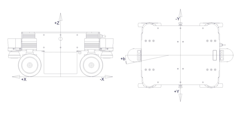
Coordinate system of MPO-700
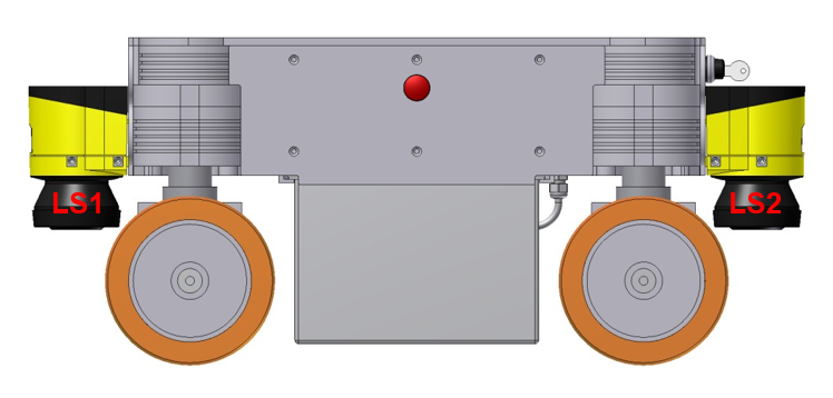
Positions of the laser scanners
| Sensor | Symbol | X-pos. | Y-pos. | Z-pos. | b-angle |
|---|---|---|---|---|---|
| Front center laser scanner | LS1 | 360 | 0 | 181 | 0 |
| Rear center laser scanner | LS2 | -360 | 0 | 181 | 180 |
| Front left laser scanner | (Option) | 327 | 277 | 201,5 | 45 |
| Rear right laser scanner | (Option) | -327 | -277 | 201,5 | 225 |
Electrical Properties and Miscellaneous Data
Properties of Internal Components
All data are taken from the respective data sheets.
| Description | Units | Value |
|---|---|---|
| Motor power | W | 400 |
| Rated motor speed | rpm | 3000 |
| Rated motor torque | Nm | 1.27 |
| Maximum motor torque | Nm | 2.32 |
| Encoder resolution | Increments/Revolution | 10000 |
| Gear ratio of orientation drives | 1 | 19:1 |
| Gear ratio of traction drives (stage1) | 1 | 15:1 |
| Gear ratio of traction drives (stage2) | 1 | 2:1 |
| Rated battery voltage | V | 48 |
| Maximum battery voltage | V | 59 |
| Battery capacity | Ah | 28 |
Other Properties
| Description | Units | Value |
|---|---|---|
| Weight | kg | 142 |
| Expected working time | a | 10 |
Communication To Internal Devices
RelayBoard
The Neobotix RelayBoard communicates with the platform’s on-board computer via a USB connection. Detailed information on the RelayBoard and the protocol can be found in its documentation (available on request).
Motor Amplifiers
All motor amplifiers and the platform’s on-board computer are connected to the same CAN-bus and set to a baud-rate of 1 MBaud. The amplifiers’ settings might need to be changed to match the communication requirements of the used control software.
The configuration software “Composer” from Elmo Motion Control can be used to configure, test and retune all motor amplifiers. Each amplifier can be connected to a COM-port (57600 Baud, no parity) of the configuration computer which runs the “Composer” by using an adapter cable. Please contact Neobotix in case you need to modify the controllers’ settings.
The documentation of the motor amplifiers (“Whistle” WHI 10-60) and the latest version of the configuration software can be found on the homepage of Elmo Motion Control. An introduction on how to configure the Omni Drive Modules can be found here.
The amplifiers use the CANopen protocol for CAN communication. The node IDs are as follows. All amplifiers use group ID 30.
| Device | Position | Traction drive ID | Orientation drive ID |
|---|---|---|---|
| A2 | Front left | 2 | 1 |
| A3 | Rear left | 4 | 3 |
| A4 | Rear right | 6 | 5 |
| A5 | Front right | 8 | 7 |
Connectors
See chapter Connectors.