

Operating Elements
The locations of the basic operating elements of the MPO-700 are shown in the picture below.
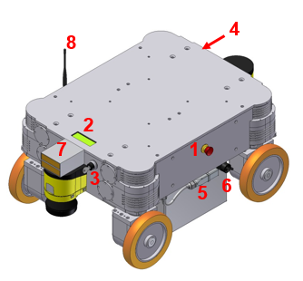
Basic control elements of the MPO-700
| 1 | Emergency stop button |
| 2 | LC-Display |
| 3 | Key switch |
| 4 | Computer access |
| 5 | Battery connector |
| 6 | Charging connector |
| 7 | Charging contacts |
| 8 | Antenna of the radio controlled emergency stop system |
Emergency Stop Buttons
When one of these buttons is pressed the robot is immediately set to emergency stop. All drives are disconnected from power supply. This state can be reset by unlocking the emergency stop buttons and turning the Key Switch clockwise to position II for a few seconds.
Key Switch
See Key Switch.
Charging Connector
This connector provides direct, not fuse protected access to the battery. The battery charger can be plugged in here. Please see the chapter Maintenance to know more.
Charging Contacts
These contacts can be connected to the battery via a high power relay if the MPO-700 has been prepared for use of the automatic charging station.
LC-Display
This display shows the most important status information. A detailed description of the LCD can be found in LC Display.
Access to the On-Board Computer
All peripheral connections of the on-board computer are accessible at the front of the platform.