neo_linear_axis
Linear axis is an add-on component for the Neobotix mobile platforms. This documentation gives you an overview of the linear axis ROS package.
neo_linear_axis package contains the hardware component for the linear axis. In the ros2_control framework, hardware component is one of the modules in the frameworks architecture, which is responsible for establishing communication between the physical hardware. These components are created as a plugin, making them modular and independent of other components in the system, thus allowing the linear axis to be easily integrated with any robot arm that has ROS 2 support. Further, ros2_control environment supports different controllers that is capable of sending position, velocity and torque commands to the hardware.
The hardware component for the linear axis is defined in the URDF under the
linear_axis_slide_joint tag.
More about hardware components can be found here.
Note
The linear axis with the EMROX version mentioned here is an heavily customized version for a unique use-case and the values in the URDF might not match with the other EMROX versions.
Sensors
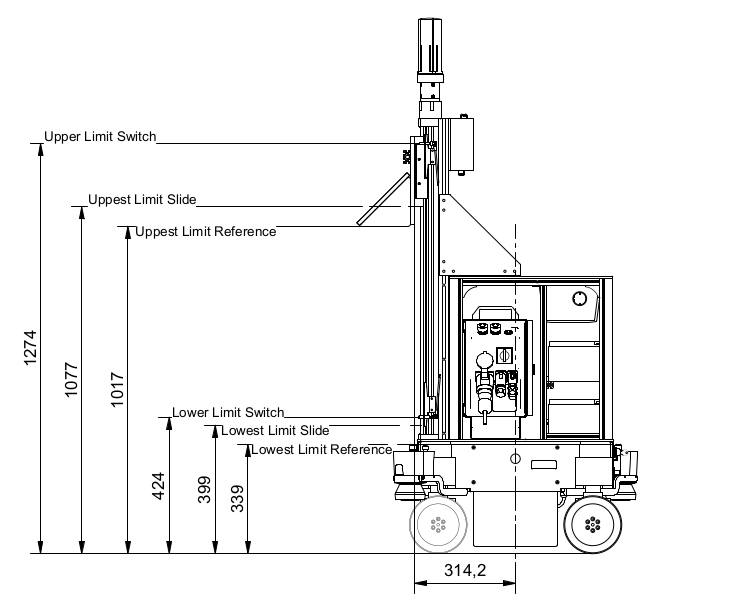
The linear axis consists of two limit switches placed at the lower and the upper end of the linear axis.
Sensor elements are also configured has hardware components. gpio tag has been utilized for defining the limit switches in the URDF. More information regarding hardware_interface types can be found here.
Configuring the Package
By default the URDF of the Neobotix robot contains the necessary links, joints and the URI to the meshes of the the axis.
For mpo_700
The URDF of the robot can be found under
your_robot/robot_model/mpo_700/mpo_700.urdf.
The config file for the joint trajectory controllers can be found under
your_robot/configs/controller/controller.yaml. The controller is named as
linear_axis_controller, which is inturn set to the type
joint_trajectory_controller/JointTrajectoryController.
For ROX
The URDF of the robot can be found under
ros2_workspace/src/rox/rox_description/urdf/rox.urdf.xacro.
The xacro for the linear axis can be found under
ros2_workspace/src/rox/rox_description/urdf/xacros/linear_axis.xacro.
The config file for the joint trajectory controllers can be found under
ros2_workspace/src/rox/rox_bringup/configs/ur/ur_controller.yaml. The
controller is named as linear_axis_controller, which is inturn set to the
type joint_trajectory_controller/JointTrajectoryController.
The configs for reading the GPIO (Limit Switches) controller can also be found under the same file ur_controller.yaml
Please look into ros2_control website for the details about the controller parameters
Note
It’s advised not to add and tune any of the parameters that is not the delivered configuration. Please consult with us, if you have any special questions with related to the configuration.
There are also pre-defined and custom parameters for the hardware components, which can be tuned from the URDF depending upon the application. The list of parameters are as follows:
The max velocity, upper and the lower limit of the linear axis is represented under the linear_axis_slide_joint:
For mpo_700
<limit lower="0.0" upper="0.68" effort="0.0" velocity="0.15"/>
For ROX
<limit lower="0.0" upper="0.77" effort="0.0" velocity="0.15"/>
Attention
Mechanically, the position of lower limit switch and the upper limit switch are can be phsically shifted depending on the application. Please change the upper and lower limit in the URDF according to your application.
Attention
Please note that, the lower limit should always point to the position where slide meets the lowest limit switch and the upper limit should point to the position where slide meets the upper limit switch.
Note
A safety mechanism is in place, that does not allow the slide to move beyond the position of the limit switches.
Custom parameters
| Field | Description | Default Value |
|---|---|---|
| can_iface | Can interface to which the motor is connected | can0 |
| timeout | Motor time out | 0.2 |
| control_rate | Motor cycle rate for reading data | 100.0 |
| initial_pose (for mpo_700) | Initial pose represents the start pose, which the linear axis move to after homing | 0.1 |
| initial_pose (for ROX) | Initial pose represents the start pose, which the linear axis move to after homing | 0.02 |
Launching
Neobotix platforms with Linear axis by default would have been already configured with steps defined above. The controller manager package enables the necessary hardware interface, JointStateBroadcaster and the Controllers.
Please refer the delivery guide regarding the activation step of your linear axis hardware interface.
If it’s a linear axis without an arm attached, the homing process will be initiated immediately after the robot bringup.
If it’s a linear axis with an arm attached, the homing process will be initiated after the necessary hardware interfaces are activated.
Attention
The JointTrajectoryController is initialized, configured and set to inactive state on bringup. JTC does not have to be active while the linear axis is homing. Keeping it active would cause the axis to go the 0.0m position after reaching the pre-configured initial pose. In contrary JTC will hold the position, when it is activated, once the complete homing process is finished.
In order to activate the controller
ros2 control set_controller_state linear_axis_controller active
More about ROS 2 CLI Framework.
Once the linear_axis_controller is activated, you will be able to send the necessary trajectory either through rqt_joint_trajectory_controller or through MoveIt, which will be discussed later.
Note
rqt_joint_trajectory_controller is utilized only for quick prototyping. It is strongly recommended either to use the ros2 action interface for sending the goals to axis or using the MoveIt to plan and send trajectories to the linear_axis_controller.
Start the rqt_joint_trajectory_controller using the following command
ros2 run rqt_joint_trajectory_controller rqt_joint_trajectory_controller
Select the controller manager and the controller. Then specify the goal position for your linear axis.
Attention
While sending goals using the rqt_joint_trajectory_controller at a speed scaling of 50 %, the axis is expected to oscillate while reaching the goal location. We observed that, the oscillation reduces by adjusting the goal tolerances. However no oscillations were inferred with the pre-configured parameters while the speed scaling was set to 100% nor neither while using MoveIt.
The joint state about the linear axis can be read in the joint_states topic.
The joint state message contains the position and velocity of the linear axis.
If you also want to read the state of the limit switches, you can read the state
from the dynamic_joint_states topic. Note dynamic_joint_states also
contains the position and the velocity of the linear axis. First index is the
limit switch mounted to the top part of the linear axis and the second index is
the limit switch mounted to the bottom part of the linear axis.
Once the JointTrajectoryController has been activated, the linear axis can be controlled using the MoveIt. Please refer to the MoveIt documentation for more information about the MoveIt.
The MoveIt package can be launched using the following command
Attention
Not valid for the ROX robot with Linear axis and dual arm support as we have configured it with neo_rox_moveit2 package.
ros2 launch neo_linear_axis move_group.launch.py
Note
The MoveIt launch file is configured to load the necessary MoveIt Controllers. Please do not change the configuration of the launch file.
Once the MoveIt is launched, it is also required to start the RViz for MoveIt. The RViz can be started using the following command
ros2 launch neo_linear_axis moveit_rviz.launch.py
By default, we have configure the linear axis group with 2 pre-poses. The first
pre-pose, top would take the robot all the way to the top, i.e. to the upper
limit switch. The second pre-pose, down would take the robot 0.1 m above the
lower limit switch.
Note
In order to achieve the full speed using MoveIt, please set the speed scaling to 100% in the MoveIt GUI.
Known issues
Attention
Not valid for the ROS versions after Humble.
JTC keeps sending the last velocity command, even after cancelling the goal in MoveIt. This is an issue originated in the ROS 2 control. More about it can be read from here: https://github.com/ros-controls/ros2_controllers/issues/683 Therefore, the temporary workaround for this was to compare the velocity commands and stop the motion.
Attention
The workaround solution might stop the axis briefly, while executing the MoveIt / JTC goal. This issue will be fixed in the next versions of the ROS 2 control.
Note
Neobotix will remove the workaround solution once the issue is fixed in the ROS 2 control.
The permanent fix can be found here: https://github.com/ros-controls/ros2_controllers/pull/801