

Transport
Note
The corresponding conditions of the MPO-700 also apply and can be found at Transport.
Unpacking and Assembly
The mobile robot MMO-700 is packed in a rugged wooden box which can be reused for future transports.
Carefully lift the control cabinet onto the platform’s top plate and position it as shown in the figure. Make sure that the countersunk holes in the cabinet’s base plate are aligned with the threaded holes in the platform’s top plate.
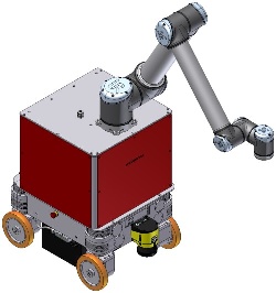
Controller cabinet and robot arm mounted to mobile platform
Now fasten the control cabinet to the mobile platform using the counter sunk screws that were included in delivery. The cover plates at the front and the sides of the control cabinet (marked in red in the picture) can be removed to provide easy access to the inside of the cabinet.
If the UR10e controller box was shipped separately, place it inside the cabinet and fix its base to the cabinet’s base plate with four M6 screws and washers. Then connect the black AC power cable and the cable with the white Molex connector to the appropriate connectors of the cabinet.
If the robot arm was shipped separately, position it on top of the control cabinet as shown above. Then fasten it securely using the M8 screws included in the delivery. Finally plug the robot arm’s cable into the socket at the underside of the controller box.
Connect the cables inside the control cabinet to the appropriate plugs of the mobile platform. Please see the electrical circuit diagram for details.
Installing the Additional Battery Pack
In order to extend the robot’s uptime, a second battery set can be installed into the controller cabinet. Before installing the auxiliary batteries, please turn off the robot and fully charge both the batteries that are currently used in the robot as well as the additional battery pack.
Warning
It is very important to fully charge both sets of batteries before connecting them. This will prevent internal currents between battery sets of different charge levels. Such currents may cause overheating and damage to the robot.
For charging the auxiliary batteries please use the adapter that was included in delivery to connect the battery charger directly to the green 2 pin power connector -X42 inside the cabinet.
Remove the front plate of the controller cabinet and place the batteries inside the aluminium frame on the cabinet’s base plate, with the battery cables facing to the right side of the robot.
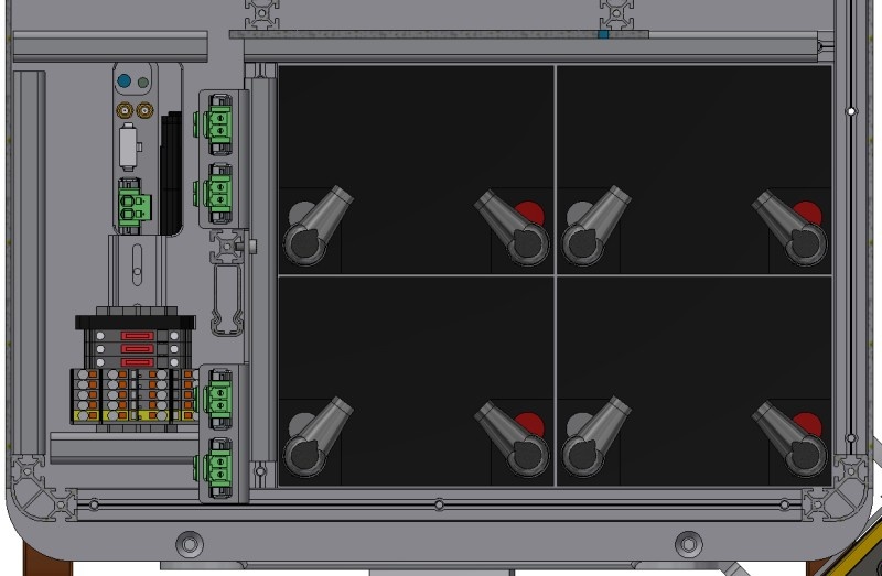
Position of the auxiliary batteries and battery connectors
Plug the battery cables into the four green connectors inside the cabinet. The connectors are protected against wrong polarity.
Now put the front and side plates back in place, fasten them securely and start the robot.
Danger
When the auxiliary batteries have been used, the robot must only be recharged by connecting the battery charger to the robot manually or by using the automatic charging station. Do not recharge either set of batteries individually by connecting them to the battery charger directly.
Three ATO fuses (80 V) inside the cabinet protect the electrical system from excessive currents. Please see the electrical circuit diagram for details.